
Understanding Processes and Enabling New Applications Using Air Bearing Positioning Systems
To fully comprehend a process, it is fundamentally important to understand and precisely observe the temporal parameters of the process. However, when high velocities are involved, even devising the method of observation can be very complicated.
With faster motion, such as on the subatomic scale, researchers must manage with the so-called pump-probe experiment. This technique is comparable to using a camera to take a series of photos with a fast shutter speed. Controlled, coordinated ultrashort laser pulses lasting only a trillionth of a second provide successful analysis. The delay between the pulses is usually generated by a delay line stage.
Advancement into Electron Dynamics
State-of-the-art technique for delay line stages in pump-probe experiments is based on mechanical guide and drive systems. These systems enable the observation of dynamics in samples in the femtosecond regime (atomic motion) on a timescale up to the picosecond range.
These systems are currently reaching their limits with regard to minimum incremental motion (MIM), which is on the order of less than 100 nm (doubled optical beam path). These systems can therefore only achieve a temporal resolution of > 0.7 fs. This is insufficient for tracking the dynamics of electrons, which are on the order of attoseconds (1 as = 0.000 000 000 000 000 001 s).
The Nobel Prize in Physics 2023 illustrates that the spectroscopic door to direct observation of electron dynamics has opened. This places new requirements on delay line stages that cannot be met by conventional systems with regard to the MIM (a few dozen nanometers) and the travel accuracy.
The Pump-Probe Setup
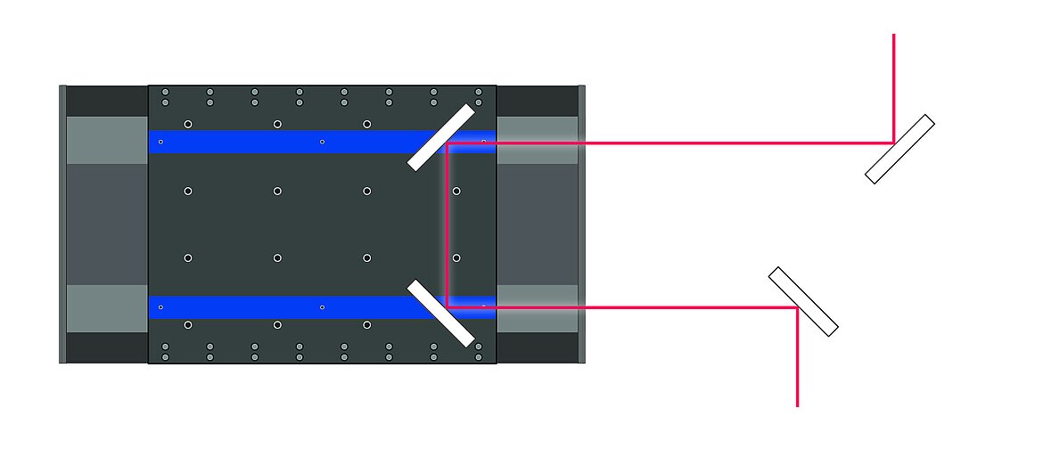
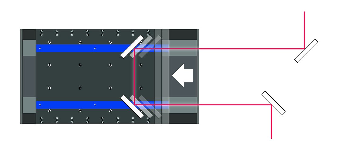
In a pump-probe setup, two coordinated pulses separated by a time delay are applied to the same point on the sample. The first pulse, also known as the pump pulse, excites the sample. The delayed probe pulse captures the excitation of the system based on the delay. The type of pulse used, such as a laser pulse or X-ray pulse, is a subordinate element of the setup.
One potential application is the observation of energy levels in solids or the alteration of the structure of electrons following strong excitation.
In this application, the following two points are fundamentally important:
- The MIM for achieving the temporal resolution required for the processes to be observed
- That the pump pulse and probe pulse are incident upon the same point on the sample every time
This means that both the lowest MIM possible and the travel accuracy of the delay line stage are critical to achieving meaningful results. Even minor parasitic movements such as pitch and yaw as well as the straightness and flatness of delay line stages have substantial effects that must be considered and compensated for. This is because the beam path is generally several meters long.
Because of imprecisions in the process, researchers must make compromises during measurement to minimize the influence of a wandering probe pulse. First, only homogenous samples or homogenous points on a sample are analyzed. Second, the pump pulse is not focused as intensely as the probe pulse so that a larger area of the sample is excited. This ensures that the excited area will be hit every time even with a drifting probe pulse.
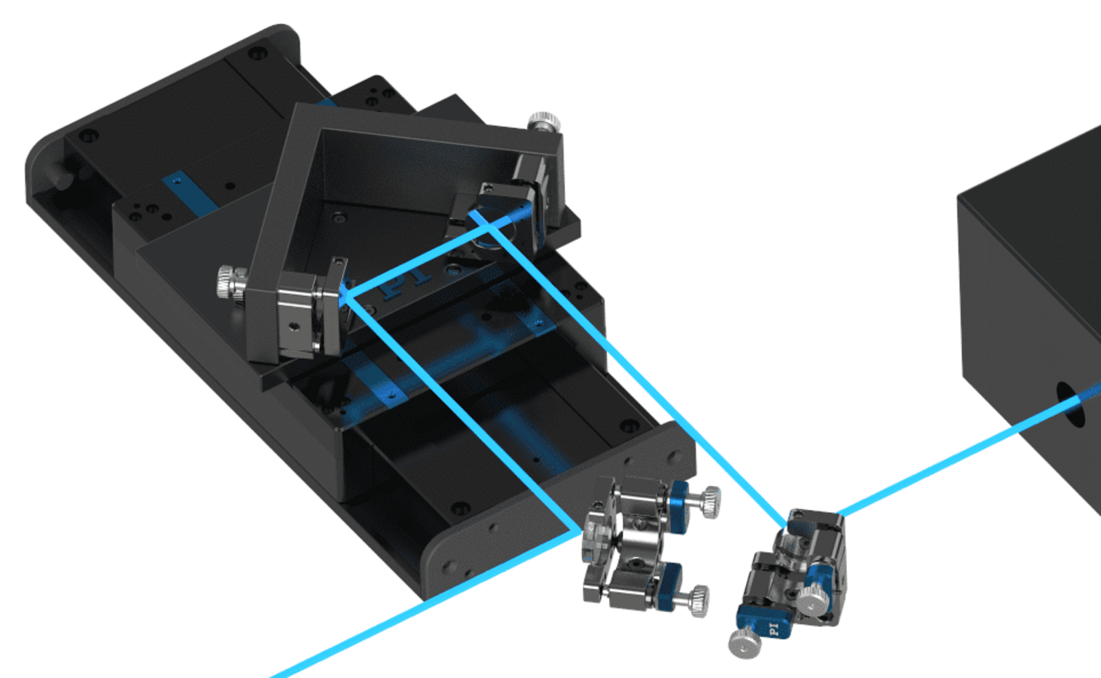
Air Bearing Systems Open the Door to the World of Electrons
This is where >> PI's air bearing systems come into play. The friction-free drive principle enables minimum incremental motions around 10 nm. This corresponds to an optical path length of approximately 66 as (doubled path due to forward and backward travel of the beam). With this technology, motion errors are typically around 0.1 µm (straightness/flatness) and 0.5 arcseconds (pitch/yaw) per 25 mm. Compared to mechanical guide concepts, this corresponds to a reduction by approximately a factor of 10.
This considerable improvement in travel accuracy enables smaller excitation areas and enables the analysis of samples down to the atomic level. A decreased focus spot also enables more energy to be introduced into the sample at a point, increasing excitation.
This resolution and travel accuracy can also be achieved with piezo-based systems. However, such systems have a travel distance limit of 1 mm, which corresponds to a maximum delay of 6.6 ns. Dynamics on a longer timescale with corresponding higher travel accuracy can only be achieved with electromagnetic drive solutions on air bearings.
